Conveyor Roller Drawing: Ideas, Models, Components, and Builder

Conveyor systems are integral components of material handling processes, used extensively in industries ranging from mining to packaging. At the heart of these systems are conveyor rollers, which facilitate the smooth and efficient movement of goods across extensive networks. The efficiency and effectiveness of a conveyor system heavily depend on the precision and quality of its rollers, making them critical for operational success.Conveyor roller drawings and 3D models play a pivotal role in the design and engineering phases of conveyor system development. These drawings provide detailed specifications and dimensions required to manufacture rollers that meet exacting standards. Furthermore, 3D models help in visualizing and simulating the conveyor’s performance before actual production begins. By employing detailed conveyor roller drawings, engineers can foresee potential mechanical failures and design inefficiencies, thus optimizing the conveyor’s design and functionality. This not only enhances the system’s efficiency but also extends the lifespan of its components.
The Basics of Conveyor Roller Drawings
Understanding the basics of conveyor roller drawing is essential for professionals in the material handling and design industries. These drawings are not just sketches but are detailed graphical representations that depict the dimensions, materials, and other specifications necessary for manufacturing conveyor rollers accurately.
What is a Conveyor Roller Drawing?
A conveyor roller drawing is a detailed blueprint used by engineers and designers to specify the geometric and functional details of conveyor rollers. Find ideas about conveyor systems and roller conveyors, including royalty-free vector art, graphics, and illustrations of robotic factory conveyor lines. These drawings are typically created using computer-aided design (CAD) software, such as AutoCAD. They provide all the necessary details to ensure that rollers are manufactured to meet exact specifications with high precision. This includes dimensions, materials used, surface finish, and sometimes even the type of bearings that should be used in the roller assembly.
Purpose of Using AutoCAD 2D and 3D in Roller Conveyor Design
AutoCAD is frequently used to create conveyor roller drawings because it allows for precise control over complex geometries and can easily toggle between 2D and 3D views. 2D drawings are essential for flat representations and are simpler to produce, making them suitable for initial drafts and basic layouts. However, 3D models are invaluable for visualizing how the roller will function within the entire conveyor system. Using 3D models, designers can simulate and analyze the mechanical behavior of rollers under different conditions, which is crucial for ensuring reliability and functionality.
Types of Conveyor Roller Drawings Available
The types of conveyor roller drawings can vary depending on the complexity of the conveyor system and the requirements of the project. Common types include:
- 2D Detail Drawings: These are the most fundamental form of conveyor roller drawings, showing all the essential measurements and machining details. They typically include orthographic projections, cross-sectional views, and component lists.
- 3D CAD Models: These models provide a three-dimensional representation of conveyor rollers, offering a more comprehensive view than 2D drawings. They are particularly useful for assembly checks, interference inspections, and digital testing of the roller’s integration with other system components.
- Installation Drawings: These drawings are used to assist in the correct installation of rollers within the conveyor framework and to ensure proper alignment and tensioning.
- Assembly Drawings: Often used together with 3D models, these drawings show how different parts of the roller fit together and may include detailed instructions for assembling the roller unit.
AutoCAD 2D download options are readily available and provide a straightforward approach for those beginning to work with conveyor roller drawings. These downloadable templates can be customized and are a good starting point for most conveyor design projects.
By comprehensively understanding the basics of conveyor roller drawing, designers and engineers can effectively communicate their specifications to manufacturing teams, leading to better-constructed conveyor systems that stand up to operational demands. This foundational knowledge not only enhances efficiency in the design and manufacturing processes but also helps in troubleshooting and maintenance long after the conveyors are integrated into daily operations.
Accessing Free Conveyor Roller Drawings
Accessing free conveyor roller drawings can significantly cut costs during the preliminary design stage of a conveyor system. These resources are invaluable for small businesses or individual engineers starting out in the conveyor design field. They provide a solid foundation for understanding the design process and are also helpful for educational purposes.
Resources for Free Conveyor Roller Drawings
Several online platforms offer free conveyor roller drawings and CAD models which can be downloaded and incorporated into design projects. These resources typically come in a variety of file formats that are compatible with most CAD software, facilitating easy integration. Some reputable sources for these drawings include:
- TraceParts: An online engineering platform that provides free CAD drawings, including conveyor roller drawings. Users can select from various components and download them in multiple formats suitable for most CAD programs.
- 3D ContentCentral: A free service for locating, configuring, downloading, and requesting 2D and 3D parts and assemblies, which also includes a wide range of conveyor roller models, all of which are free to download after registering on the site.
- CAD Blocks Free: This website offers a vast collection of free CAD blocks, including conveyor roller drawings. These are available as direct downloads and are extremely useful for quick design needs.
- GrabCAD Community Library: A great resource where engineers around the world share their CAD files, including conveyor systems and rollers, which are free to download and can be modified to suit specific requirements.
How to Download Free Roller Conveyor CAD Models
Downloading free conveyor roller drawings or CAD models is straightforward:
- Select a Resource: Choose a website that hosts free CAD models that meet your requirements.
- Search for Conveyor Rollers: Use the search function on the website to locate conveyor roller drawings. It is often possible to specify the type of CAD file you prefer (e.g., AutoCAD, SolidWorks).
- Register/Sign In: Some sites require users to register to download files. This typically involves providing an email address and creating a password.
- Download: Once you find the conveyor roller drawing you need, click on the download button. Ensure you select the correct format that is compatible with your CAD software.
Benefits of Utilizing Free Resources for Preliminary Designs
Using free conveyor roller drawings offers several advantages, especially during the initial phases of design:
- Cost Efficiency: Reduces the upfront cost of design by eliminating the need to produce detailed drawings from scratch.
- Time-Saving: Accelerates the design process as engineers have immediate access to a library of pre-made drawings that can be easily modified to fit specific needs.
- Flexibility: Provides a variety of options and components that designers can experiment with without financial commitment.
- Risk Reduction: Allows for extensive preliminary testing and simulation using detailed models to identify potential issues before committing to final production.
Incorporating free conveyor roller drawings into the design process not only streamlines development but also enhances the designer’s ability to create more effective and reliable conveyor system solutions. These resources are particularly valuable in reducing the time and cost associated with the conceptual and preliminary design stages.
Detailed Look at Conveyor Roller Drawings and CAD Models
In the realm of conveyor belt system design, conveyor roller drawing and modeling serve as critical tools. While 2D drawings offer a fundamental view, 3D CAD models provide an in-depth perspective necessary for more complex analyses and real-world applications. This section explores the distinctions between these two types of drawings and the practical applications of 3D models in designing conveyor systems.
The Distinction Between 2D Drawings and 3D CAD Models
Conveyor roller drawings in 2D provide basic, essential details about dimensions and assembly instructions, typically displayed in tables and standard views (top, side, front). These drawings are sufficient for general planning and are widely used for initial sketches or when simplicity and speed are priorities.
On the other hand, 3D CAD models of conveyor rollers offer a comprehensive view, encapsulating the complete geometry which allows for simulations and functional testing before physical prototypes are made. These models, as outlined in the roller conveyor design guide, can be rotated and viewed from any angle, providing a holistic understanding of the conveyor roller’s design and functionality.
Gravity Roller Conveyor CAD Drawings and Their Applications
Gravity roller conveyors are widely used for their simplicity and efficiency. The CAD drawings for these systems are particularly important as they need to precisely represent physical realities to ensure functionality without power aids.
Warehouse Item Sorting Systems:
- Application: Used in warehouses to sort packages based on size or destination.
- Benefit: Precise conveyor roller spacings in the CAD model help minimize item falling and maximize sorting speed.
Assembly Line Foundations:
- Application: Basic framework for various assembly lines in manufacturing settings.
- Benefit: Detailed models ensure that components align perfectly, reducing the risk of production errors.
Loading and Unloading Bays:
- Application: Facilitates the loading and unloading of goods, particularly heavy items.
- Benefit: The CAD drawing specifies roller thickness and density to handle specified weights, enhancing safety and efficiency.
Food Processing Lines:
- Application: Used in the food industry to transport products through different processing stages.
- Benefit: The drawing includes specifications for materials that are food-safe and easy to clean.
The Significance of Precise Modeling in the Accurate Representation of Conveyor Systems
Precise 3D modeling plays a critical role in the effective implementation of conveyor systems.
Custom Conveyor Configurations:
- Need: To fit specific spatial constraints.
- Significance: Precise models allow designers to customize configurations that maximize space use and efficiency.
Integration with Other Machinery:
- Need: Conveyor systems often need to integrate with robotic arms or other automated machinery.
- Significance: Accurate 3D models ensure seamless integration, preventing mechanical clashes and maintaining workflow continuity.
Stress and Load Testing:
- Need: To predict how the conveyor will perform under maximum expected loads.
- Significance: Detailed CAD models can be used in simulations to view stress points and potential failure spots, which can be addressed before production.
Maintenance Planning:
- Need: To establish effective maintenance schedules.
- Significance: With precise models, maintenance teams can predict wear and tear on various parts, scheduling interventions that minimize downtime and extend the conveyor’s lifespan.
These examples underscore the vital role that detailed conveyor roller drawings play not just in the design and manufacture of these systems, but also in their ongoing maintenance and integration into larger logistical operations. The move from 2D to 3D models marks a significant step up in the ability to innovate and improve upon traditional conveyor system designs.
The Variety of Conveyor Roller Drawings and Models Available
The diversity in conveyor roller drawing models facilitates the design of systems tailored to specific industrial needs, enhancing functionality and efficiency. This section delves into the various types of roller conveyor models available, particularly highlighting the versatility offered by both gravity and powered conveyor systems.
Different Models of Roller Conveyors
Roller conveyors are broadly categorized into gravity and powered systems, each serving distinct operational roles with various CAD models available for design and implementation. Below is a comparative table highlighting key aspects of these models:
Availability of Roller Conveyor 3D Models for Intricate Design Evaluations
The availability of detailed 3D CAD models for roller conveyors allows for intricate design evaluations that are crucial in optimizing the conveyor system. These models provide a virtual testing ground where different scenarios can be simulated to see potential impacts on the system’s efficiency and reliability. Utilizing conveyor roller drawings in 3D helps engineers:
- Visualize spatial relationships and clearance
- Simulate operational flows
- Test the conveyor under various load conditions
- Adjust the design to meet specific requirements
Featured CAD Models for Specific Types of Roller Conveyors
Various CAD models cater to specific conveyor types and industries, enhancing the relevance and application of these designs in real-world scenarios.
Gravity Roller Conveyor for Distribution Centers:
- CAD Model Features: Simplified 2D and 3D models with adjustable roller spacings and heights.
- Application: Efficiently moves boxes and pallets down the line with minimal energy use.
- Industry Use: Logistics and warehousing for sorting and staging products before shipment.
Powered Roller Conveyor for Automotive Assembly Lines:
- CAD Model Features: Detailed 3D models showing motor placements and roller divisions.
- Application: Transports car parts through assembly, handling heavy components smoothly.
- Industry Use: Automotive manufacturing, where precision and handling of heavy loads are critical.
Flexible Roller Conveyor for Food and Beverage Manufacturing:
- CAD Model Features: Highly customizable 3D models adaptable to curved paths and varying widths.
- Application: Moves food products through processing areas, adaptable to space constraints.
- Industry Use: Food and beverage industries that require high hygiene standards and flexibility in conveyor layouts.
Telescopic Gravity Roller Conveyor for Retail Stocking:
- CAD Model Features: Extendable 2D and 3D models that adjust in length to accommodate different stocking areas.
- Application: Used for loading and unloading goods to and from back storage rooms to shelves.
- Industry Use: Retail environments where space is limited and flexibility is needed in conveyor setup.
These conveyor roller drawings and models are essential tools in the planning and execution phases of conveyor system development. They provide a detailed preview of the functional and physical aspects of the conveyors, ensuring that the systems are designed to meet the specific needs of the industry and operational criteria. Utilizing these diverse models allows companies to enhance efficiency, reduce costs, and implement robust material handling solutions tailored to their unique logistical challenges.

Components of Conveyor Roller Drawing
The design and functionality of conveyor systems critically depend on the precise configuration of their rollers. Understanding the conveyor roller drawing and its components is essential for engineers and designers to optimize the system’s efficiency and durability. This section details the various components of conveyor rollers, explores the significance of each part, and discusses the materials used, including special coatings for specific applications.
Describing the Conveyor Roller Parts Names
A typical conveyor roller drawing includes several key components, each with a specific function and requirement. The primary parts of a typical roller include:
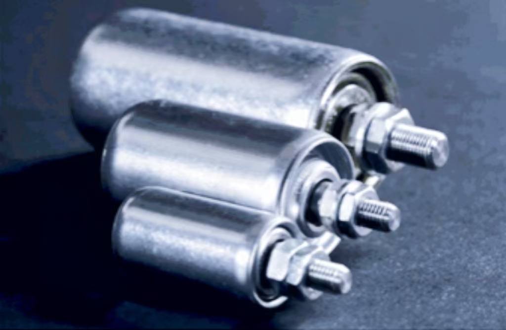
- Tube: The main body of the roller that contacts the conveyed material. It is cylindrical and can vary in length and diameter.
- Shaft: A rod that runs through the tube’s center and supports the tube. It is critical for attaching the roller within the conveyor roller frame.
- Bearing and Bearing Housing: Bearings allow the roller to turn smoothly with minimal friction. The housing protects and secures the bearings in place.
- Seals: Seals are used to keep out contaminants such as dust and water, thereby protecting the bearings and prolonging the roller’s life.
- End Cap/Labyrinth Seal: These components are fitted on the ends of the roller to hold the bearings within the tube and prevent the ingress of contaminants.
Each of these components is crucial for the proper functioning of a conveyor roller and is detailed explicitly within conveyor roller drawings for precise manufacturing and assembly.
The Importance of Each Part Through Detailed Drawings
Conveyor roller drawings not only depict the assembly but also highlight the critical tolerances and specifications for each part:
- Tube: Must be straight and robust enough to handle the load. The diameter is chosen based on the load and the type of material conveyed.
- Shaft: Its size and material determine the roller’s load-bearing capacity. It must align perfectly with the tube for smooth operation.
- Bearings and Housing: Correctly specified bearings reduce maintenance needs and prevent failures. The housing must ensure a firm fit while allowing the bearings to operate at their best.
- Seals: Proper seals are vital for protecting the bearings from environmental challenges and extending the operational life of the roller.
Detailed conveyor roller drawings provide the necessary information to manufacture these components to meet exact specifications, ensuring reliable and efficient conveyor operation.
Different Materials for Rollers, Including Coated Conveyor Rollers for Special Applications
Rollers can be made from various materials, each selected based on the application requirements:

- Steel Rollers: Commonly used for their strength and durability. Suitable for heavy loads and high impact conditions.
- Plastic Rollers: Lighter and quieter than steel, plastic rollers are suitable for lighter loads and are more corrosion-resistant.
- Rubber-Coated Rollers: These provide additional grip and noise reduction, ideal for sensitive or irregular-shaped items.
For special applications, rollers might be coated or treated to enhance their performance:
- Galvanized Rollers: Treated with a layer of zinc to resist corrosion, suitable for wet or hostile environments.
- Polyurethane Coated Rollers: Offers excellent grip and durability, reducing slippage and wear, especially useful in the packaging industry.
- Teflon-Coated Rollers: Used in applications requiring high heat resistance and a non-stick surface, such as baking or drying processes.
Conveyor roller drawings must specify the material and any coatings accurately to ensure that the rollers meet the operational demands of the conveyor system. These details help in selecting the right components that will not only handle the physical loads and environmental conditions but also optimize the conveyor’s overall performance.
Detailed conveyor roller drawings and a thorough understanding of the components’ functions and materials are fundamental in designing and operating efficient conveyor systems. These drawings ensure that all parts are correctly specified and fit together seamlessly, leading to enhanced system reliability and longevity.
Enhancing Designs with Advanced Models for Conveyor Roller Drawing
The development of advanced models and the integration of modern technology have significantly enhanced the capabilities and efficiency of conveyor systems. This section explores the advancements in roller conveyor diagram designs, including the use of motors and sophisticated 3D modeling techniques that aid in the virtual testing and refinement of conveyor systems during the product development cycle.
Advancements in Roller Conveyor Designs
Recent advancements in roller conveyor designs have transformed traditional conveyor systems, making them more efficient and adaptable to various operational needs. Key developments include:
- Motorized Rollers: The inclusion of motors within the rollers themselves has led to the creation of motor-driven roller conveyors. These conveyors are more energy-efficient, provide better control of movement, and can handle varying speeds and loads with precision. Conveyor roller drawings for these systems are complex and include detailed specifications for electrical components and motor assemblies.
- Smart Rollers: Equipped with sensors, these rollers can monitor system performance, track the condition of the conveyor, and even predict maintenance needs. Smart rollers are becoming increasingly important in automated and data-driven manufacturing environments.
- Adjustable Roller Conveyors: These conveyors can adjust the spacing between rollers or the pathway angle to accommodate different product sizes or processing needs, which are often highlighted in conveyor roller drawings to ensure precise modifications and scalability.
The Role of 3D Models in Testing Designs Virtually
3D modeling, particularly the use of conveyor roller 3D model free downloads, plays a pivotal role in the design and testing of conveyor systems:
- Visualization and Simulation: 3D models allow designers to visualize the conveyor in a simulated real-world environment, where they can test different configurations and operational settings without the need to build a physical model.
- Interference and Tolerance Checking: Using 3D models, engineers can perform virtual tests to check for part interferences and tolerance issues, which helps in optimizing the design for better performance and reliability.
- Integration Testing: Conveyor roller drawings in 3D formats can be used to test how new roller designs integrate with existing conveyor system components or with other machinery in a production line.
- Prototyping: 3D printed prototypes of rollers can be created from CAD models, providing a cost-effective and quick method for physical testing and validation of the design before full-scale production.
Incorporating Roller CAD Models in Product Development Cycles
Incorporating conveyor roller CAD models into product development cycles enhances the design process significantly:
- Iterative Design: CAD models facilitate iterative testing and refinement of designs. Changes can be made quickly in the model, and their impacts can be assessed virtually, which accelerates the development process.
- Collaborative Design: CAD models can be easily shared with team members regardless of their physical location, which supports a collaborative design approach. This is particularly useful in multi-disciplinary teams where mechanical, electrical, and control engineering aspects need to be integrated.
- Documentation and Standardization: Conveyor roller drawings provide a detailed and standardized record of the design, which is crucial for manufacturing, assembly, and future maintenance works.
- Cost Reduction: By identifying design issues early in the development process through virtual tests and simulations, significant cost savings can be achieved by reducing the need for multiple physical prototypes and avoiding potential failures.
The use of advanced CAD models and roller conveyor diagram techniques is revolutionizing the conveyor design process, making it faster, less expensive, and more effective at meeting specific operational requirements. These tools not only improve the design phase but also enhance the overall lifecycle management of the conveyor system by facilitating easier updates, maintenance, and scalability.
Utilization in Industries About Conveyor Roller Drawing
The application of conveyor roller drawings and CAD models across various industries showcases their critical role in solving complex design challenges. This section provides insights into specific case studies where CAD models have been pivotal, with a focus on the usage of gravity roller conveyor CAD designs in distinct industrial settings.
Case Studies: CAD Models in Industrial Conveyor Design
Conveyor roller drawings and 3D CAD models have been instrumental in addressing and resolving numerous industrial challenges.
Automotive Parts Assembly Line:
- Challenge: The need to handle various sizes and weights of automotive parts with minimal product damage.
- Solution: Utilization of motorized roller conveyors designed through CAD models to adjust speeds and operate with precision.
- Outcome: Enhanced efficiency in the assembly line with reduced manual handling and lower product damage rates.
Pharmaceutical Packaging Line:
- Challenge: Requirement for extremely clean and contaminant-free conveyors to handle sensitive pharmaceutical products.
- Solution: Implementation of stainless steel gravity roller conveyors with detailed conveyor roller drawings specifying non-corrosive materials and smooth surfaces.
- Outcome: Successful deployment of a hygienic conveyor system that meets stringent industry regulations and prevents product contamination.
E-commerce Fulfillment Center:
- Challenge: Efficient handling of a high volume of small, diverse packages.
- Solution: Custom-designed, scalable conveyor systems developed using 3D CAD models to facilitate sorting and packaging processes.
- Outcome: Streamlined operations that improved sorting efficiency by 40% and reduced parcel handling times.
Food and Beverage Production Line:
- Challenge: Conveying different types of food products requiring varying speeds and hygiene levels.
- Solution: Gravity and powered roller conveyors with easy-to-clean surfaces and quick configuration changes, detailed in conveyor roller drawings.
- Outcome: A versatile conveyor system that can adapt to different production needs without compromising food safety.
Gravity Roller Conveyor CAD and Its Industrial Relevance
Gravity roller conveyors are a staple in many industries due to their simplicity and efficiency. The relevance of roller conveyor diagram for gravity systems is particularly notable in the following settings:
- Warehousing and Distribution: Facilitates the easy movement of goods from storage to shipping. Gravity roller conveyors are ideal here due to their low maintenance and ability to move items quickly with minimal energy.
- Manufacturing Facilities: Used for assembly lines where parts need to be manually accessed throughout the assembly process. The CAD models help in customizing the conveyor layout to fit specific workflows and space constraints.
- Food Processing: In industries where sanitation is crucial, gravity roller conveyors made from food-grade materials are preferred. CAD models specify dimensions and materials that meet health and safety standards.
- Retail Back-End Operations: Used in stock rooms and loading areas to transfer goods to and from the sales floor efficiently. CAD-designed gravity conveyors optimize space use and improve labor efficiency.
In each of these applications, conveyor roller drawings and CAD models provide the detailed specifications required to customize the systems to meet operational demands and integrate seamlessly with other equipment. The precision and adaptability offered by CAD technologies allow industries to not only solve logistical challenges but also to innovate and improve upon traditional conveyor system designs. The continued development and refinement of these models are essential as industries evolve and their needs become more complex.
Transform your operations with our superior conveyor rollers. Act today!
Practical Tips for Downloading and Using Conveyor Roller Drawing
Effectively utilizing conveyor roller drawings in both AutoCAD 2D and 3D formats can significantly enhance the design and customization process of conveyor systems. This section offers a step-by-step guide on how to download and use these drawings, outlines best practices for integrating them into the design process, and provides advice on customizing these models for specific projects.
Step-by-Step Guide on Downloading and Using Roller Conveyor Drawing AutoCAD 2D and 3D Models
Downloading Drawings:
Identify a Source:
- Choose a reputable online platform that offers conveyor roller drawings. Websites like TraceParts or 3D ContentCentral are good starting points.
Search for the Specific Model:
- Use the search function to find the specific type of roller conveyor drawing you need. You can usually filter results by the type of conveyor (gravity, motorized, etc.), the file type (2D or 3D), and other specifications.
Select the File Format:
- Depending on the software you’re using (e.g., AutoCAD), select the appropriate file format. Common formats include DWG for AutoCAD and STEP or IGES for other 3D modeling programs.
Download the File:
- Once you’ve found the right roller conveyor drawing, proceed to download it. Ensure that you have the necessary permissions or software to open the file.
Using Drawings:
Open Your CAD Software:
- Launch the CAD program (e.g., AutoCAD) and open the downloaded file.
Review the Drawing:
- Examine the conveyor roller drawing for any specifics about dimensions, materials, or assembly instructions. This information is crucial for integration into your design.
Modify If Necessary:
- Depending on your project’s requirements, you may need to modify the drawing. Use the CAD software’s tools to make adjustments to dimensions or change materials.
Integrate into Your Project:
- Incorporate the modified conveyor roller drawing into your larger project file. Ensure that alignments and placements are correct relative to other system components.
Best Practices for Incorporating Drawings into the Design Process
- Consistency: Use conveyor roller drawings that adhere to consistent standards to ensure compatibility and reliability across various parts of the conveyor system.
- Verification: Always double-check the dimensions and specifications within the conveyor roller drawing against physical requirements and constraints of the actual system.
- Collaboration: Share the CAD files with team members to review and provide feedback, which can prevent potential issues in the design phase.
- Documentation: Maintain thorough documentation of all changes made to the original drawings, including reasons for changes and the expected impact on system performance.
Advice on Customization and Modification of the Downloaded Roller Conveyor Drawings
Customizing conveyor roller drawings is often necessary to meet specific project requirements.
Adjusting Roller Length:
- Original Need: A system requires a shorter roller than what’s available.
- Modification: Shorten the roller length in the CAD model to fit the specific distance between conveyor frames.
Material Changes:
- Original Need: The default material is not suitable for a chemical exposure environment.
- Modification: Change the material specification in the drawing to stainless steel to enhance corrosion resistance.
Adding Custom Features:
- Original Need: Need to add sensors to rollers for a smart conveyor system.
- Modification: Integrate mounts and wiring paths into the roller design to accommodate sensors.
Modifying Bearing Types:
- Original Need: Original bearings are not suitable for high-temperature applications.
- Modification: Replace the bearing type in the drawing with high-temperature resistant bearings.
Utilizing these practical tips and examples for downloading and customizing conveyor roller drawings can significantly aid in designing more effective and tailored conveyor systems. Proper integration and modification of these drawings ensure that the conveyor will operate smoothly and efficiently, meeting all specified requirements and standards.
FAQs About Conveyor Roller Drawing
A conveyor roller is a vital component of roller conveyor systems, which are used extensively across various industries to facilitate the movement of goods and materials along a defined path. Essentially, a conveyor roller is a cylindrical tube that is mounted on bearings and held in place between conveyor frames. The primary function of conveyor rollers is to support and move the conveyor belt or the materials being transported efficiently and with minimal friction.
Conveyor rollers can vary significantly depending on their intended use, materials transported, and the environment in which they are used. They are commonly made from materials such as steel, plastic, or rubber, with each material offering different benefits in terms of strength, durability, and cost. The choice of roller type directly impacts the conveyor system’s efficiency, operational speed, and maintenance needs.
Roller conveyors are particularly popular in manufacturing and distribution facilities, where they are utilized for their simplicity and efficiency in moving products or parts from one point to another. They can be powered by motors or operate on gravity if inclined, which helps in reducing energy consumption and operational costs.
The structure of a roller conveyor system is designed to support the efficient transport of goods across various sections of a production or storage facility. The basic structure comprises several key components:
Rollers: These are the cylindrical tubes that actually move the items along the conveyor. They are mounted horizontally on the frame and can rotate freely.
Frame: This supports the rollers and is typically made from steel or aluminum profiles. The frame’s design and material are critical for ensuring the conveyor’s durability and ability to bear loads.
Bearings: Bearings are used to mount the rollers in the frame and allow them to spin freely. They are crucial for minimizing friction and wear on the rollers.
Drive Unit: In powered roller conveyors, a drive unit is used to rotate the rollers. This can be an electric motor connected to a series of rollers via gears, belts, or chains.
Conveyor Belt (optional): Some roller conveyors use belts or chains to link the rollers together, ensuring synchronous movement and better handling of materials.
The conveyor’s structure might vary slightly depending on whether it is a gravity roller conveyor (which uses the force of gravity to move materials) or a powered conveyor (which uses motors to move the rollers).
The standard conveyor roller is designed to fit the majority of conveyor systems commonly used in various industries. These rollers are typically characterized by their robustness, durability, and efficiency in handling materials. The standard dimensions and materials may vary slightly by manufacturer and specific application needs but generally include:
Diameter: The common diameters of standard rollers are between 1.9 inches to 3.5 inches.
Length: Roller lengths are usually customized to the width of the conveyor system but typically range from a few inches up to several feet.
Material: Steel is the most commonly used material for standard rollers due to its strength and durability; however, plastic rollers are also popular for lighter applications or environments where corrosion resistance is important.
The choice of standard conveyor roller typically depends on the load it needs to support, the environment in which it operates (e.g., wet, dry, corrosive), and the speed at which the system operates.
Calculating the correct specifications for conveyor rollers involves understanding several key parameters of the conveyor system. The basic formula to determine the roller length typically looks like this:
Roller Length = Between Frame Width + Bearing Width
Where:
Between Frame Width is the inside width between the conveyor frames.
Bearing Width is the total width of the bearings on both sides of the roller.
However, the calculation of other parameters like roller diameter and spacing between rollers can depend on more specific factors including:
Load per Roller: Determines how much weight each roller must support.
Roller Spacing: Based on the size of the largest load item, to prevent sagging.
Speed of the Conveyor: Higher speeds may require rollers with higher durability or special materials.
Engineers use these formulas and considerations to design rollers that are optimized for the specific conditions of each conveyor system, ensuring efficiency, reliability, and safety in operations. These calculations help in creating a well-functioning conveyor system tailored to the operational demands and workload of the industry it serves.
A conveyor roller is a cylindrical component installed in conveyor systems to facilitate the movement of goods. These rollers are critical in warehouses, manufacturing plants, and distribution centers for transporting packages, materials, and products efficiently and safely along a predetermined path.
Conveyor rollers serve multiple purposes, including reducing manual handling, improving efficiency, and enhancing the speed of operations. They help in the seamless transfer of items between different stages of production, sorting, packaging, and loading. By minimizing physical labor, they also contribute to workplace safety and reduce the risk of injuries.
To make a conveyor roller, follow these steps:
Select Materials: Choose durable materials like steel or plastic.
Cut to Size: Cut the materials to the required length and diameter.
Assemble Components: Attach bearings, shafts, and other components to the roller.
Secure Fastenings: Use screws or welding to secure parts.
Test for Quality: Ensure the roller spins smoothly and meets load capacity requirements.
Roller conveyors work by using a series of rollers mounted in a frame, allowing items to be moved manually, by gravity, or through powered means. Items placed on the conveyor move along the rollers, propelled by the force applied either manually or by a motor. The rollers’ arrangement and spacing can be adjusted based on the size and weight of the items being transported, ensuring efficient and reliable movement.
Last Updated on June 14, 2024 by Jordan Smith
Jordan Smith, a seasoned professional with over 20 years of experience in the conveyor system industry. Jordan’s expertise lies in providing comprehensive solutions for conveyor rollers, belts, and accessories, catering to a wide range of industrial needs. From initial design and configuration to installation and meticulous troubleshooting, Jordan is adept at handling all aspects of conveyor system management. Whether you’re looking to upgrade your production line with efficient conveyor belts, require custom conveyor rollers for specific operations, or need expert advice on selecting the right conveyor accessories for your facility, Jordan is your reliable consultant. For any inquiries or assistance with conveyor system optimization, Jordan is available to share his wealth of knowledge and experience. Feel free to reach out at any time for professional guidance on all matters related to conveyor rollers, belts, and accessories.

